Dahlberg  Audio  Design.
"The tall neodymium ribbon". Part 1


Welcome!
Introduction:

This series of articles will describe the making of "The tall neodymium ribbon". The description is  complete but is not intended for the absolute beginner. 

It takes some experience in handling with machines and a decent respect for the forces involved. 

The magnets used in this project produce a substantial magnetic force so you better take care about your hands etc. 

That should take care of the fact that I'm not taking any responsibility for damage or injury, whether to property, body, mind or anything else whatsoever.


This first article will be about the magnetic system and some smaller parts. Part 2 describes some woodworking and the internal wiring. 

In the third and final part the manufacturing of the ribbons are described.


Thanks to  Per "Pac" Adelson  for input, help and publication at   HiFiForum.nu

I'm starting of with some background. I have constructed a number of ribbon tweeters of different form and function over the last 15 years.  Almost all of them have shared similarities with the concept of the "Apogee Duetta", a concept that is  well suited for most people. This page on the other hand will describe the construction of a more advanced neodymium based tweeter.

Apogee was actually the inspiration for this solution as well. Apogee used a different solution for the mid section in the model "Diva". Their use of specially formed ceramic magnets was substituted in this project with  70x10x6 mm neodymium magnets. One of the advantages of this solution is that the strongest part of the magnetic force field is moved from the edge of the magnet and into the magnetic gap.

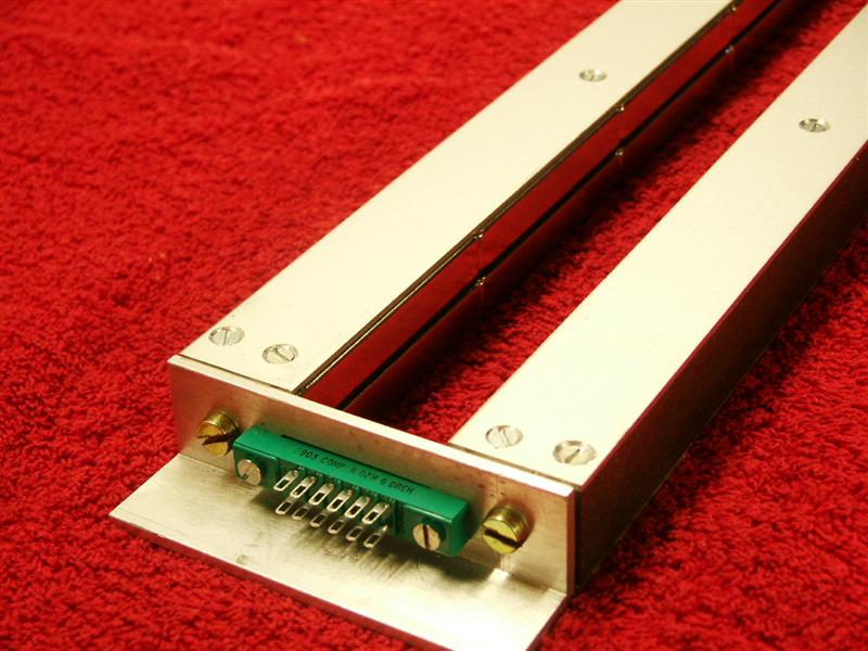
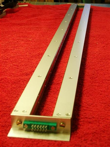
Finished result without the ribbon.

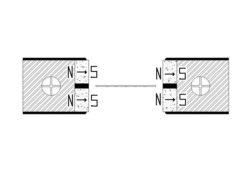
This is how they look in theory.
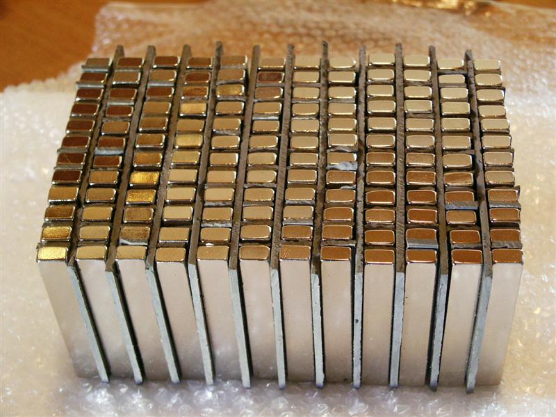
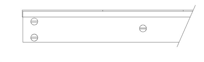
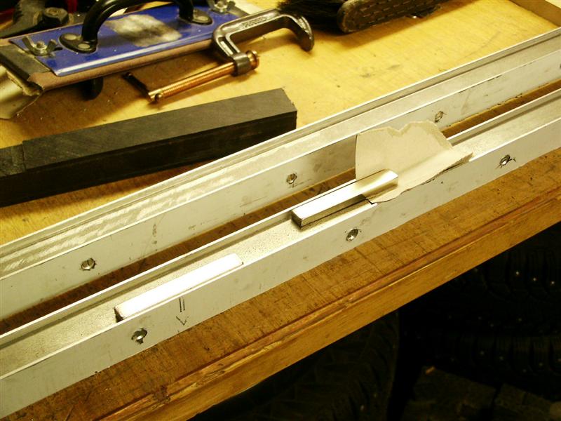
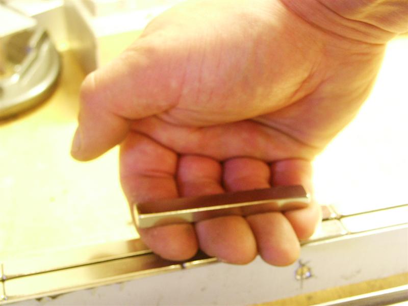

A list of things you will need:

1. Magnets for decided length. You will need 8 pieces for every 7cm of tweeter pair. Order a few spares, they can break.

2. Steel, 22x22mm that will act as pole pieces. 

3. Card edge connectors.  Hopefully you will find them at your local electronics supplier. In Sweden at Elfa. They are not essential to the construction but they work very well. Stock no: 43-760-00 at Elfa. 

4.  Aluminum strips, 1,5mm sheet metal cut too 27mm x the length.

5. Angled profile from aluminum 25x25x2mm. Will constitute short ends and fasteners for the ribbon.

6. Cable housing for the internal wiring. Maybe 12mm copper pipe from your local plumber. You will also need elbows joints.

7. Wooden details for the outside. Here the choice is yours. There are many options and I will present two different solutions.

8. The ribbons. This is described in a separate list. Look further down the page.

9. Some smaller odd parts.

Magnets

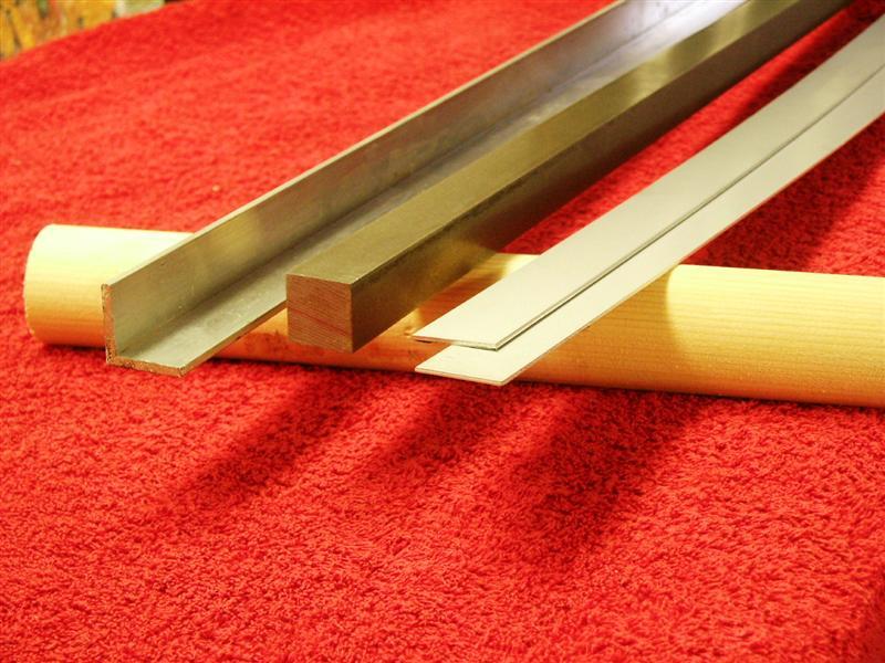
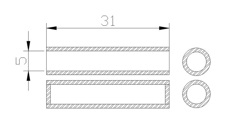
Aluminum strips, 22x22mm steel and angled profile from aluminum.

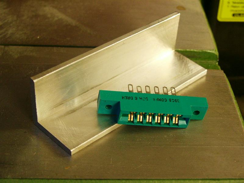
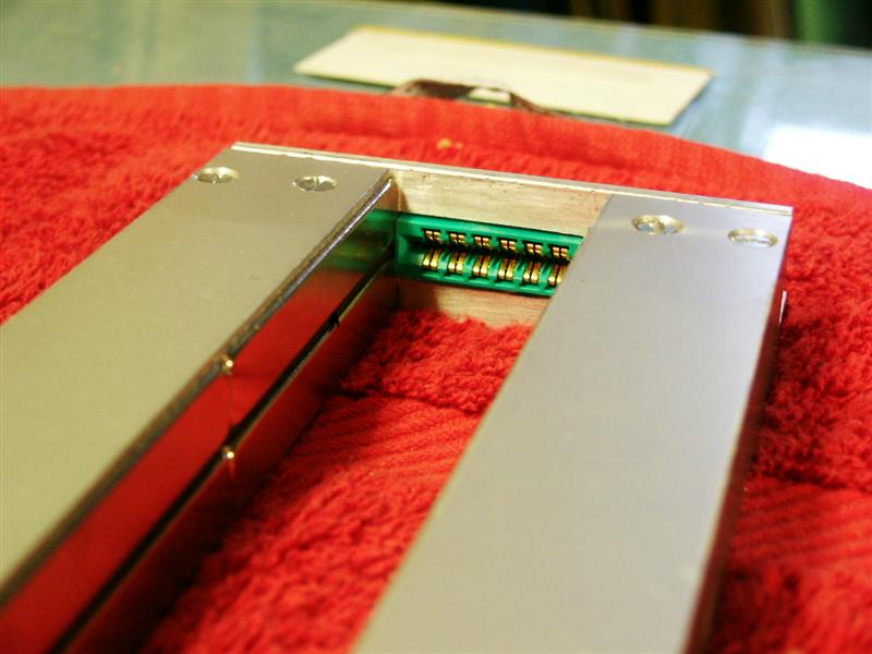
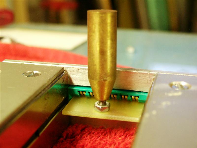
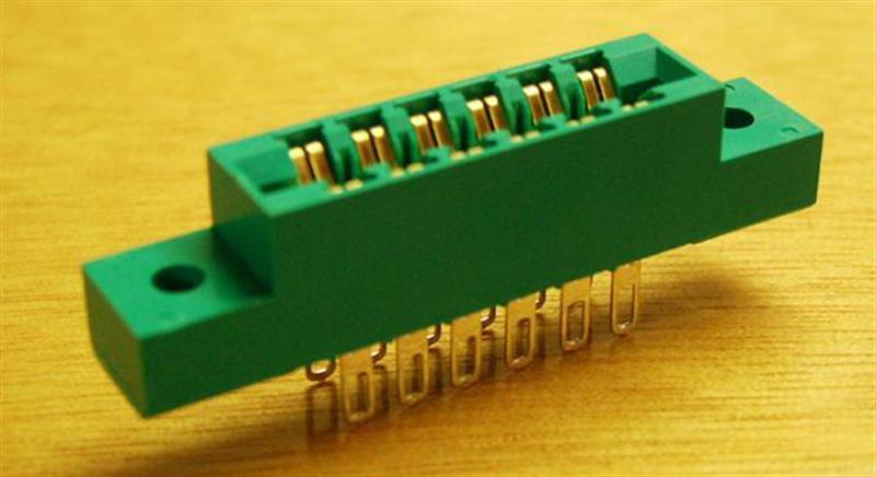
Card edge connector.

Some tools are also needed 

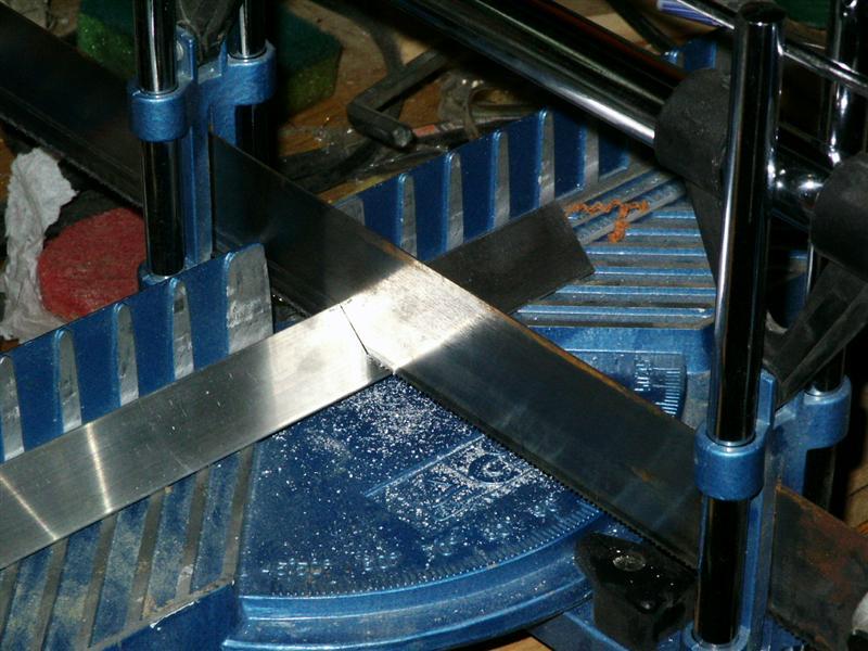
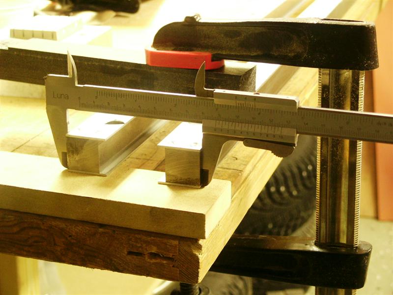
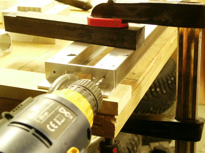
First cut the steel to the right length, a hacksaw is recommended. Take some measurements on the magnets just to be sure about the length. Calipers made from plastic are good enough and they are non-magnetic, that's not insignificant. If the steel rods turn out to be a little bit short, that's not a problem it's almost an advantage. Adjust the length with spacers. It's important that the cuts are perpendicular. T

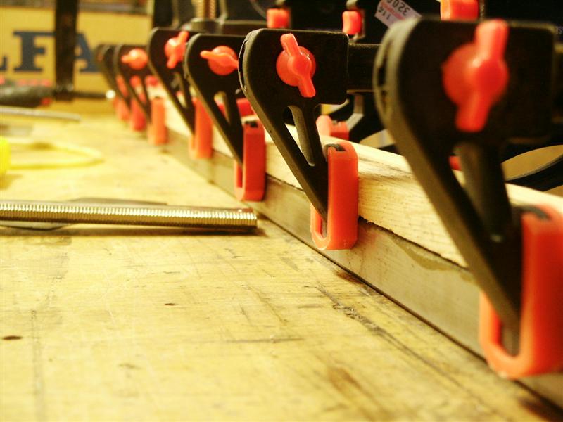
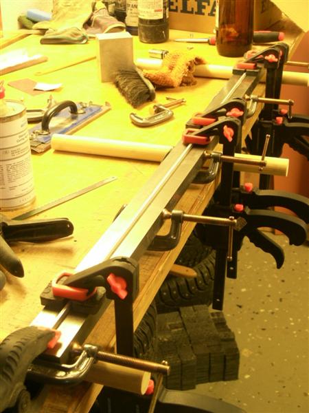
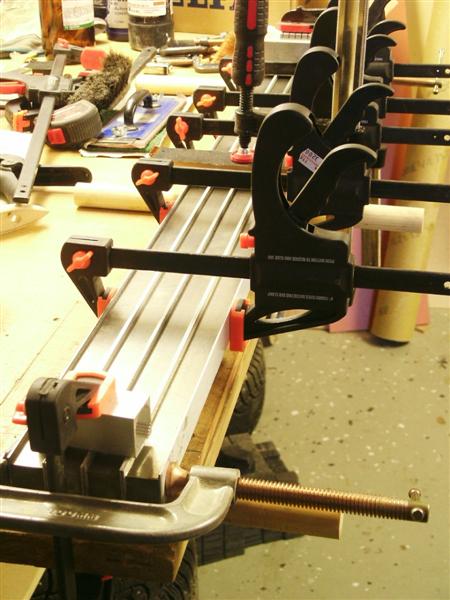
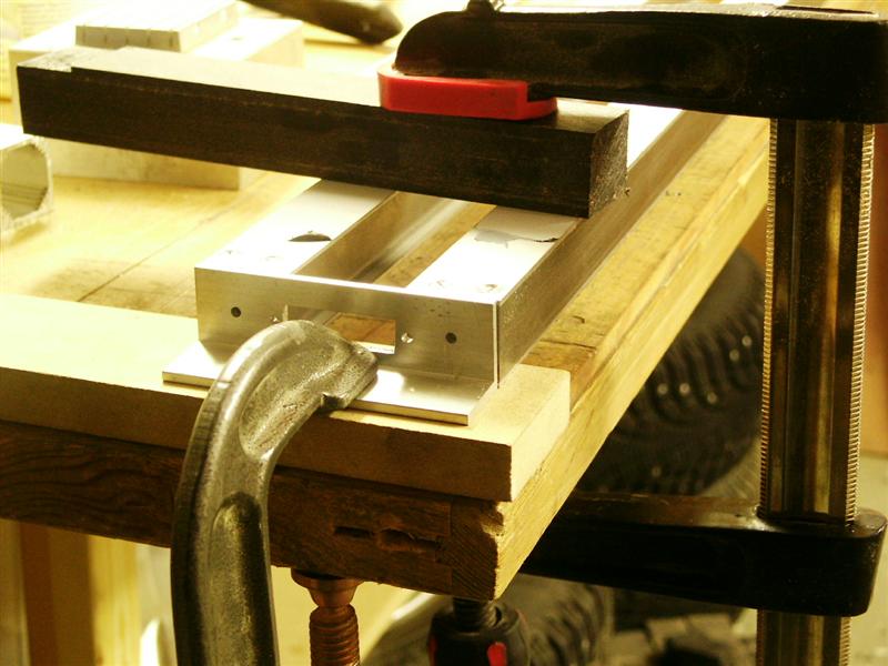
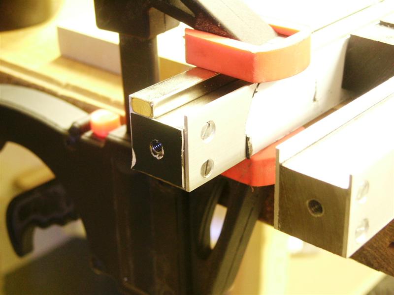
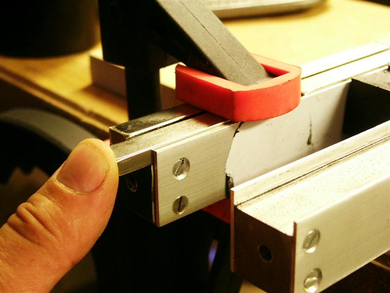
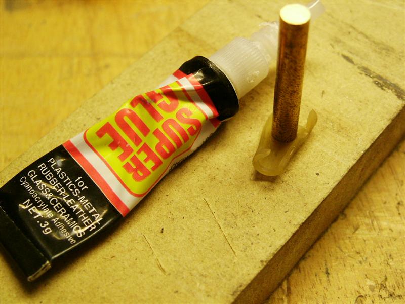
Now the aluminum strips are mounted. After a thorough cleaning of the steel you will sand two sides for improved bonding. I'm using both adhesive and bolts. The strips should also be sanded for the adhesive. Nothing strange about the gluing just make sure the strips don't slide. A lot of extra work is thereby avoided.
Now too the bolts. They are an extra precaution to make absolutely sure that the strips do not come loose.  Where to make the holes should  be apparent from the drawing. Drill 2,7 mm through all of it and tap M3 from both sides. Use a countersink. Assemble it with stainless M3 bolts. Or something similar.


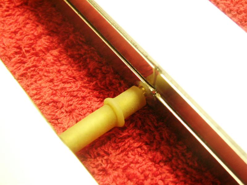
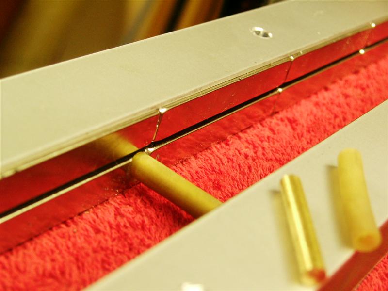
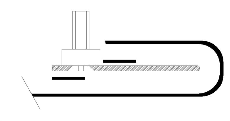
Don't glue the parts to the table the first thing you do. Notice the wooden rods.


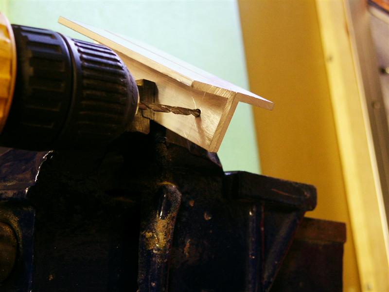
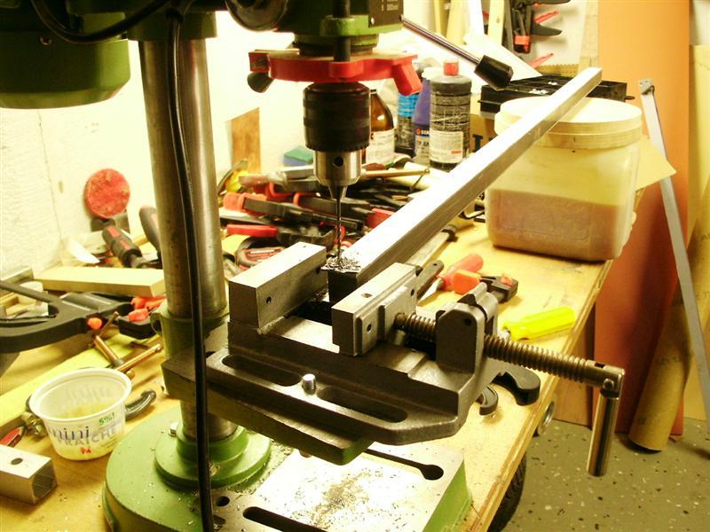
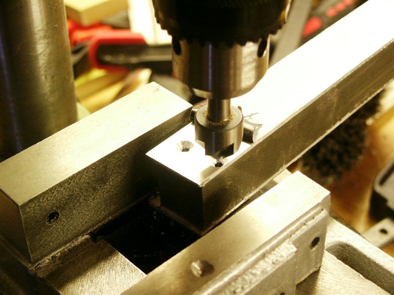
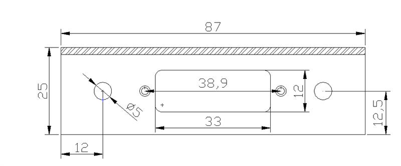
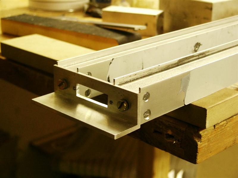
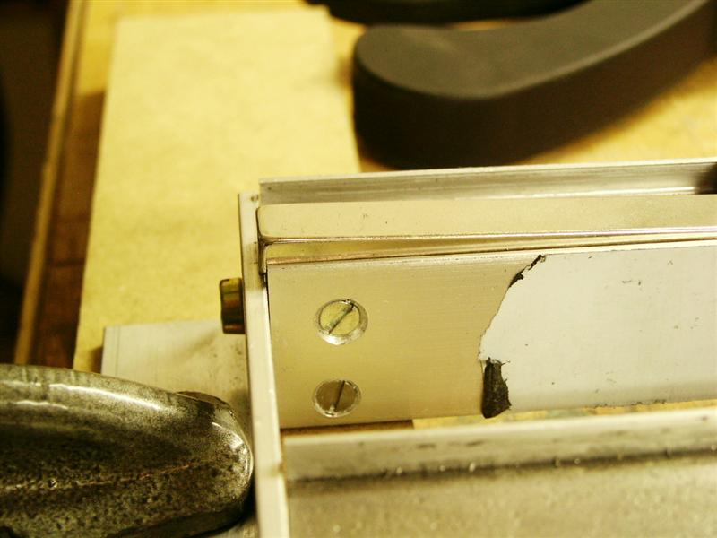
Drill 2,7 mm through all of it and thread M3 from both sides.

Countersink.


The two holes on the left have to be there because of the holes that will be drilled for the short ends. Also it improves strength where it's needed the most. 

The short ends. 
We need angled aluminum profile. Measures 87x25x25x2 mm. In that we will drill two 3mm holes that later on will be drilled to 5mm holes for joining the short ends to the steel rods.  The reason for the 3mm start is that it will work better as a guide for the drilling of the steel. Besides that there will be M3 holes and a bigger one (33x12mm) for the card edge connector. The drawing should be sufficient for the measurements. The first finished one will work just fine as a guide for the following ones.

Drawing for the short ends, follow it !

Aluminum profile under the saw .

Steel and short-ends are mounted on a bench so that everything is in place and then the holes are drilled in the steel. Start with 3mm and then remove the short ends to be able to drill 4,5mm in the steel, then thread to M5. Make sure that all holes are sufficiently deep. Now we can drill the 5mm holes in the short ends. 

Somewhat depending on the continuation, the metal-work on the magnetic circuits is done. But do not mount the magnets before you have decided on which version you are building. See the part about woodworking first.

87,5mm !!!!

Ok, comes along just fine.

Mounting the magnets. Rotate the steel-rods so that the surfaces that are going to hold the magnets are pointing upwards, lock by turning the bolts. Take a piece of cardboard or something similar and hold the magnet against the steel. When the magnet has taken hold of the steel you slide it off the cardboard and into place. The next one is placed in the same manner besides the first one, it will then push away from the first one but the aluminum strip will hold it in place. Be very careful how you turn the magnets, they are a real pain to loosen if they are turned the wrong way. I have started from the middle and worked my way outwards. This is a tricky part of the project because the magnets may  jump and turn in mid air but usually it works just fine. If they do they may break so order a few spares. The last magnet on the short end is without comparison the most difficult one but the trick shown in the picture seems to work. Magnetic direction is very important and when you hold the magnets as I do in the last picture it will turn the right way. If you turn the magnet 180 degrees it will be in the right direction for the second steel rod. 


Steel rods rotated 90 degrees and ready for the magnets.


Little bit to short steel is solved with a spacer. Cardboard in this case.

Cardboard in place. Follow the trick used to mount the last magnet.

When the magnets are in place they are secured with the help of a 2x5mm rubber strip. The idea is that the unit should be possible to disassemble but this is of course optional. You can glue the magnets if you want. I have cut strips from a rubber cloth. When you stretch these strips they shrink and then you can poke them into place between the magnets. When the strip has formed itself after the column the magnet can not rotate and therefore it can not come loose. Now it is time to loosen the locking (at least 2mm's), the magnet circuits will then turn towards each other.  When the card edge connector is attached it is time to leave the magnetic circuits for a while.

Rubber strip coming in too place. First part almost done with the card edge connector.


To keep the magnetic circuits apart and to secure the ribbon's position in the middle of the magnetic gap we have to make some brass (non magnetic) retainers. I have created mine from a 5mm dia. brass rod and I have covered them with a latex hose. Half of them are going to be just the right length for them to be squeezed by the magnets and then glued in place. The other half of them are going to be a little shorter. They will be covered with latex on the short ends as well, as a result they will be a little bit longer (not much) and you will have to push them into place with mild force (works better if you wet them a little). How many support-points you will have use for depends on how long the tweeter will be but somewhere around one for every foot is sufficient. Thus far I have tried three points for a 112 cm long one, and two points for a 105 cm version. Both of them works just fine.

The drawing. Glued in place.
Looks god so far. I'm sure you that you can figure out the rest.

For the mounting of the ribbons we need male connectors that will fit to the card edge connectors, so let's make some. From circuit-board material we cut pieces that are 22x27 mm. The copper layer shall be removed, otherwise the connectors will be to thick for the ribbon-plus-connector. The short black stripes indicate double-coated tape. Which part is the ribbon should be evident from the drawing. To create a small handle an M3 bolt is mounted (countersunk). Another recommendation is that an extension shaft is created from brass or aluminum. For instance a 10mm rod with an M3 hole at one end. It simplifies the mounting of the ribbons.


Part2  Part3

© Bengt Dahlberg & HiFiForum.nu except: Logos and Trademarks are property of their owners. All Rights Reserved